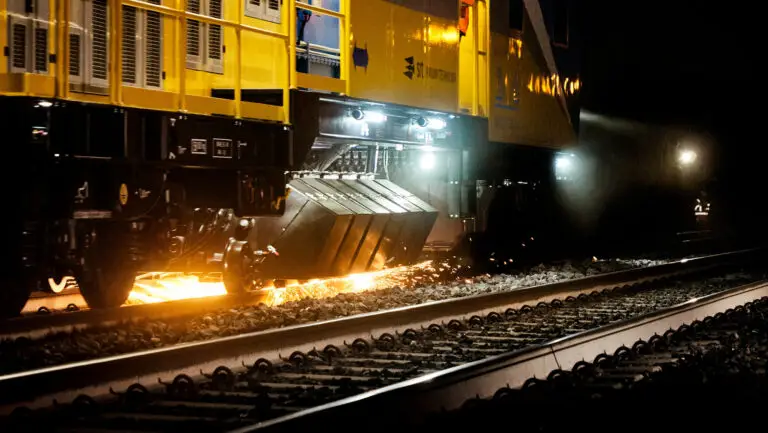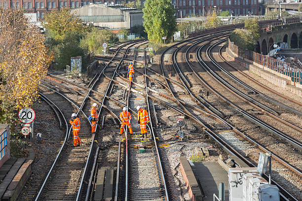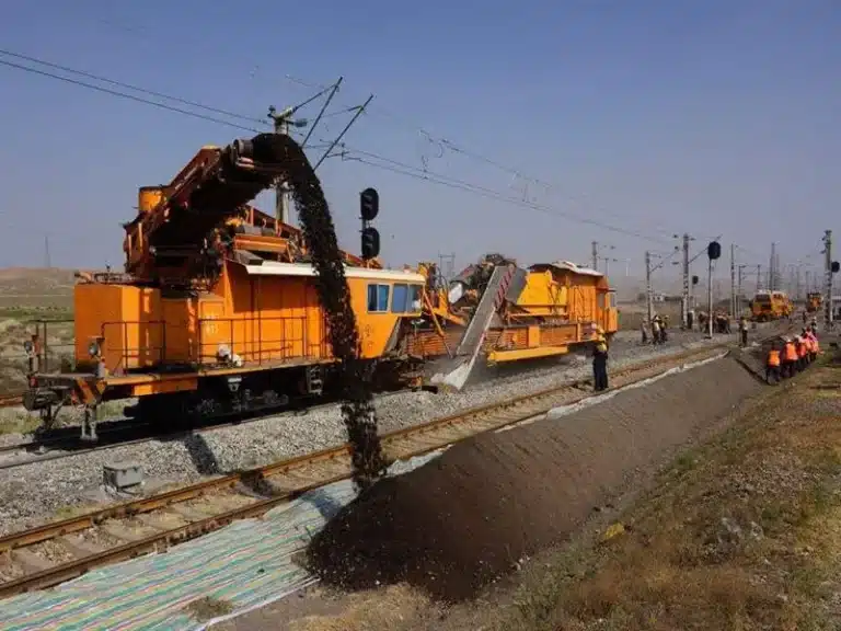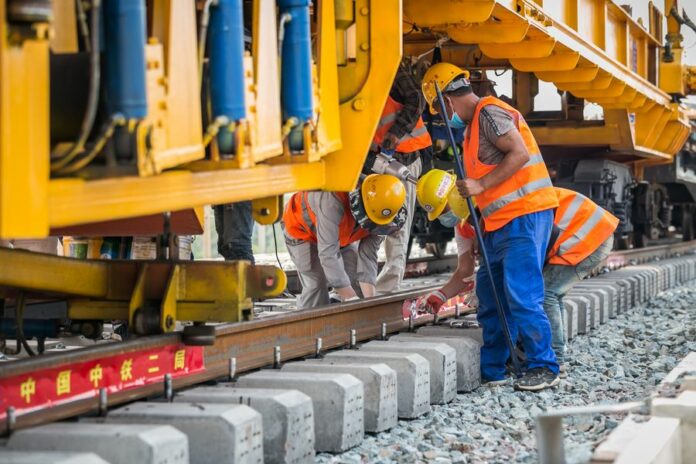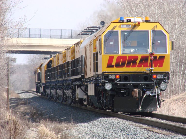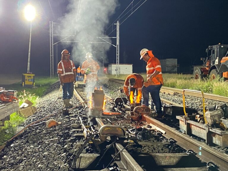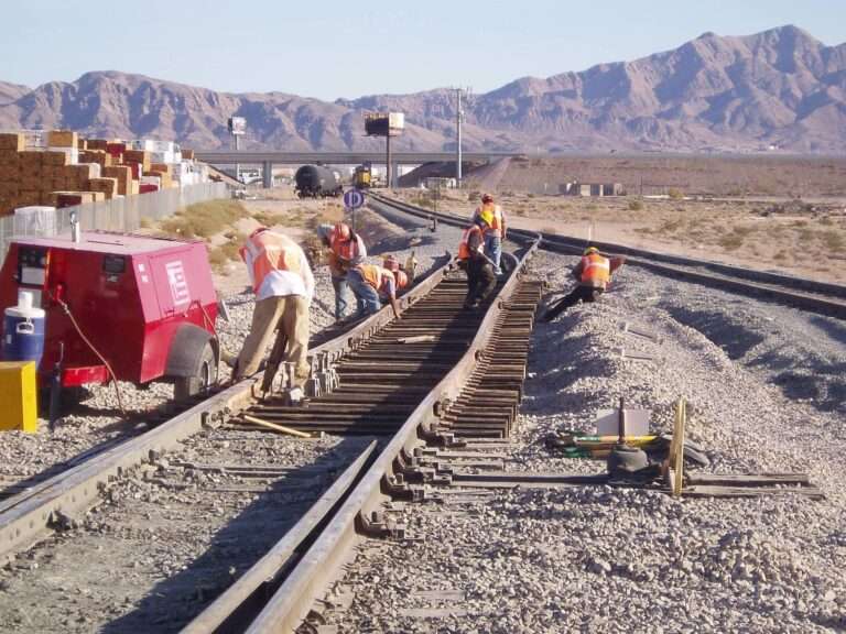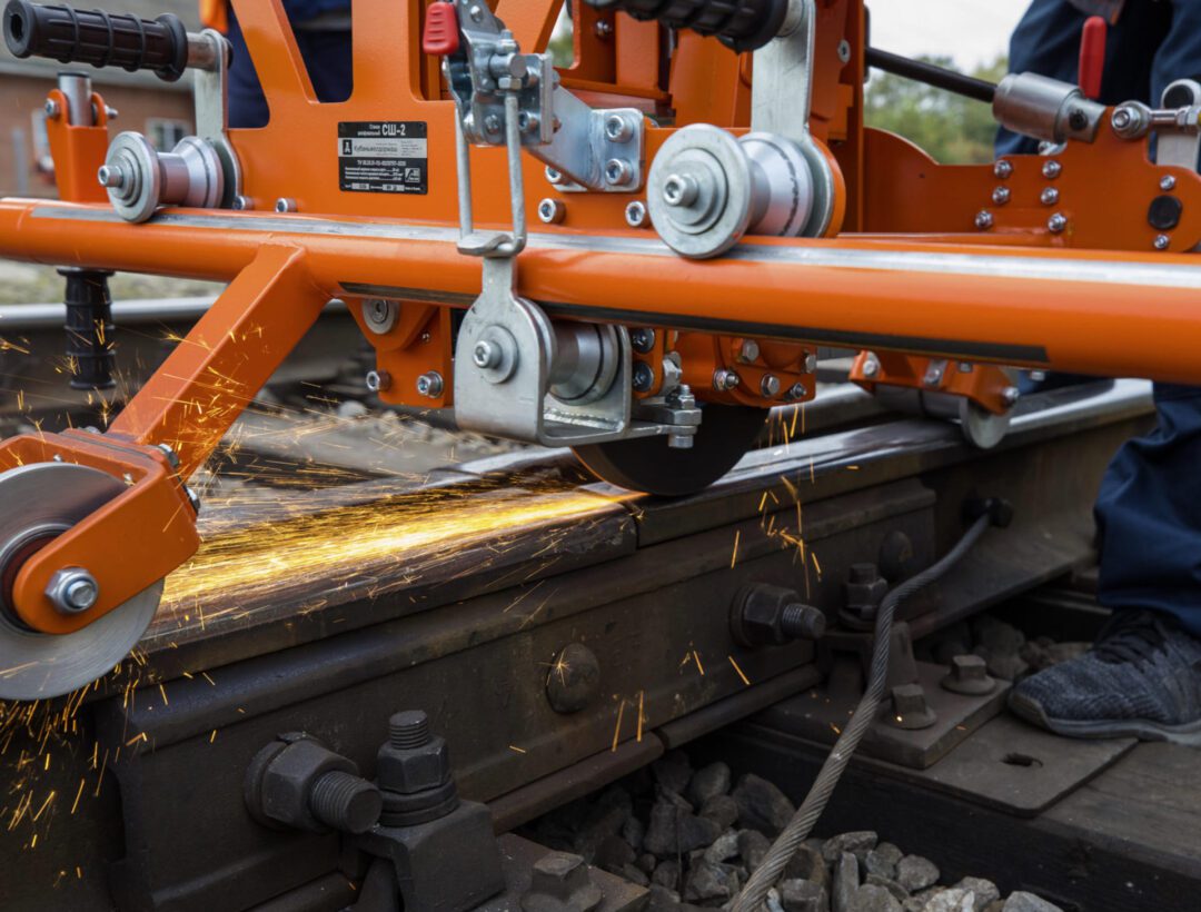
Rail track grinding is a critical component of railway line maintenance, with its significance spanning three major dimensions: safety assurance, economic efficiency, and operational performance. From a safety perspective, precise rail track grinding eliminates surface wear, micro-cracks, and metal overflow (lip formation). This prevents localized defects from propagating under repeated train loads, significantly reducing the risks of derailment and rail breaks, thus building a solid line of defense for safe operations. From an economic standpoint, scientific rail track grinding extends rail service life by 30% to 50%, reduces replacement frequency, and lowers overall track maintenance costs when executed with high-performance rail grinding wheels.. From a transport efficiency aspect, ground rails feature smooth running surfaces and precise profiles, which reduce wheel-rail friction, noise, and vibration. This not only increases train speeds and stability, but also minimizes rolling stock wear, improves passenger ride comfort, and provides foundational support for high-quality railway operations.
1. Turnout & Switch Rail Track Grinding
Before grinding, remeasure and re-verify key defects such as head checks (squats/shelving), metal overflow, and irregular contact bands (running light bands). Record baseline data prior to grinding, and mark the exact locations and boundaries for the grinding operations.
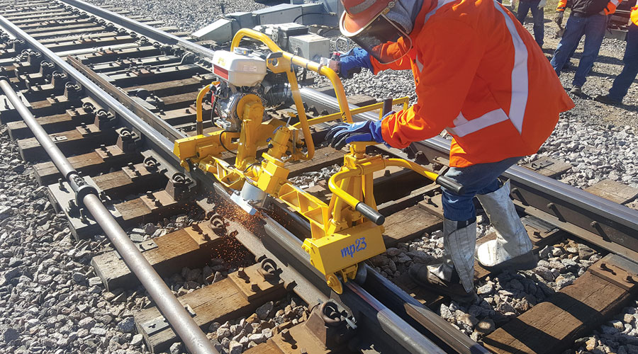
Switch Rail Grinding
Prior to grinding, throw the switch machine to ensure the switch point is in the closed position. Ensure the contact face of the grinding wheel is suspended clear of the rail before starting high-speed rotation. Adjust the height of the grinding machine, utilizing precision profile grinding wheelsto operate through angular adjustments from +60° down to -10° (adjusting the wheel angle based on actual defect conditions). Shift angles in increments of 2° to 4° per pass until defects like head checks, metal overflow, and poor contact bands are completely removed.
Stock Rail Grinding
Prior to grinding, throw the switch rail to the open position. Test-run the grinding machine, idling and running at high speed without load for approximately 1 minute. Ensure the grinding wheel surface remains suspended before entering high-speed mode. Adjust the grinding wheel height, and process through angles from +60° down to -10° (adjusted per field conditions), shifting by 2° to 4° per pass until all surface defects and irregular contact bands on the stock rail are eliminated.
2. Plain Track Rail Track Grinding
For tracks exhibiting abnormal wear or poor contact bands, use a rail profile measurement gauge on-site to analyze profile deviations between the target area and adjacent railheads. Compare data and mark the grinding location and range. (If surface scuffing or spalling is present, measure the hardness and depth prior to grinding.)
During plain rail track grinding, referring to measured profile data as the angular baseline is essential. (To explore different machine profiles and technical evolutions, check out our Rail Grinder Library.) Measure continuously during grinding to prevent over-grinding until the standard profile tolerance is reached.
When grinding surface scuffing/bruising, use a depth gauge to record maximum damage depth and check local hardness. Mark the repair zone. Calculate the required metal removal and grinding length based on depth values (the grinding transition length on a single side must be at least 5,000 times the depth of the defect). Grind the full cross-section from the gauge corner toward the field side, incrementing by 2° to 4° per pass, and smooth the transition profile to match the unground adjacent rails seamlessly.
3. Rail Weld Joint Grinding
For irregular or uneven weld joints, place the “0” mark of a 1-meter straightedge directly over the center of the weld on the peak (high joint) or trough (dipped joint) of the running surface. Measure weld peak/dip alignment using feeler gauges. Measure the gauge side alignment 16 mm below the top of the rail, record the values, and mark the grinding boundaries.
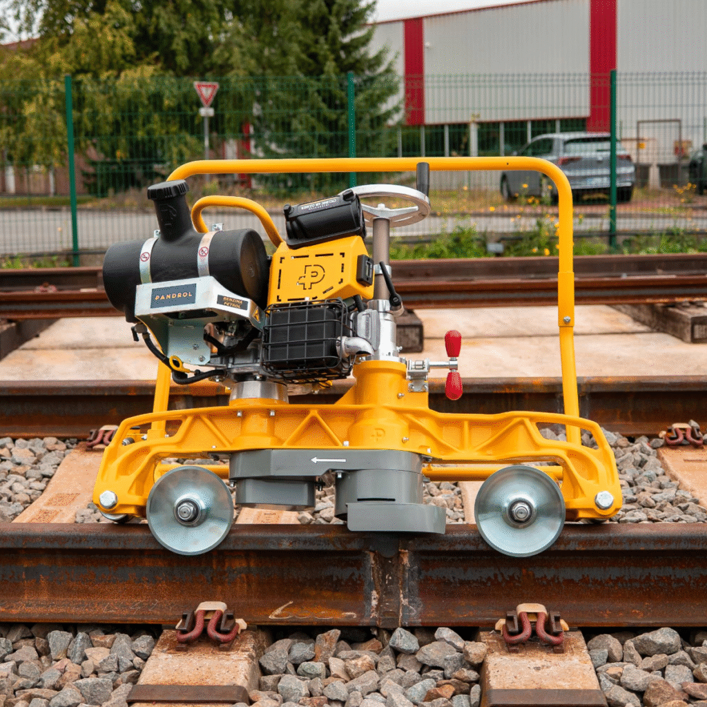
High/Crowned Weld Joints
For crowned welds, grind according to marked boundaries from the gauge corner toward the field side. Sweep angles from +45° to -10° (adjusted based on defect severity), incrementing by 2° to 4° per pass. Ensure smooth, uniform reciprocating passes and steady feed control via the lead screw until the peak is completely leveled.
Dipped/Low Weld Joints
For dipped welds and low joints, apply a feathering/tapering technique to the base metal on both sides of the weld. Determine the ramp length based on the depth of the dip. Maintain smooth reciprocating movement and precise screw adjustment while grinding from the gauge corner to the field side across angles from +45° down to -10° (incrementing by 2° to 4°). Continue until the dipped profile transitions smoothly without steps.
Irregular Weld Gauge Side
To fix irregularities on the gauge side/working edge of the weld, adjust the grinding wheel perpendicular to the working face and apply ramped grinding on both sides. Measure continuously during grinding until the alignment along the gauge edge is completely restored.
4. Post-Grinding Inspection & Acceptance Criteria
Conduct a thorough quality re-inspection after rail track grinding to check overall surface contact band consistency:
- Turnouts: Request a switch throw test to confirm smooth mechanical operation and correct contact clearance.
- Running Surfaces: On tangent tracks and the low rail of curves, the contact light band should be centered, with a measured width of 20 mm to 30 mm (using a steel rule). On the high rail of curves, the contact band should shift slightly toward the gauge side. Measure the ground profile with a profile gauge to ensure it stays within standard tolerance limits.
- Weld Straightness (over a 1-meter span): Check the inner gauge working side using a 1m straightedge and feeler gauge. Target tolerance is 0 to +0.3 mm (Note: “+” indicates concave/dip). Top running surface peak tolerance is controlled within +0.3 mm to +0.5 mm.
- Surface Quality: The ground rail surface must be free of lip/metal overflow, visible head checks, fatigue cracks, or continuous blue thermal oxidation bands. The railhead and rail foot areas must be clean of metal debris and grinding slag.